The Highs and Lows of Optical Communication: ER vs. OMA
Optical modulation amplitude (OMA) and extinction ratio (ER) are two relative measurements used to characterize fiber optic communication. While they are calculated (or measured) using the same values, they represent different results. Fiber-optic communication is based on a modulated light source transmitted over an optical fiber to a receiver. In order to ensure that the signal received is the same as the signal that was sent, specifications were established that define minimum and/or maximum values of this modulation – to know when the light was on or off and thus determine a 0 from a 1. These specifications are protocol and speed-dependent and differ not only in magnitude but also in how they’re calculated. Further, the different protocols have different standards bodies guiding them and were developed at different times all of which help explain why some network protocols use ER while some use OMA.
Drilling down into the fiber-optic communication, a digital signal is a series of ones and zeros that is generated at one point, sent over optical fiber, and received at the other end where it is used. The laser modulation is defined between a high (P1) and low (P0) output level, which represent the ones and zeros, at a specified rate that is determined by the data rate of the link. The actual output power or Tx is the biased voltage applied to the laser output while the receiver sensitivity or RX is the minimum amount of light received where the modulation can accurately be determined.
Measuring transmit characteristics are done to ensure proper performance of the device itself and specifically tie them to the receiver capabilities. Problems occur when a receiver is not able to determine whether the light level at a given time is at the high or low level. This problem manifests itself as errors in the data stream when converted back to copper. Both ER and OMA are values that, when met, establish that there is enough of a change from the high level to the low level that the receiver will be able to discern between the two regardless of whether the link is very short, or the link approaches the maximum allowable link length. With the parameters for operation defined, then, the parameter for successful transmission then is either the ratio between high and low power or ER (ER= P1/P0)or the difference between high and lower power or OMA (OMA= P1 – P0).
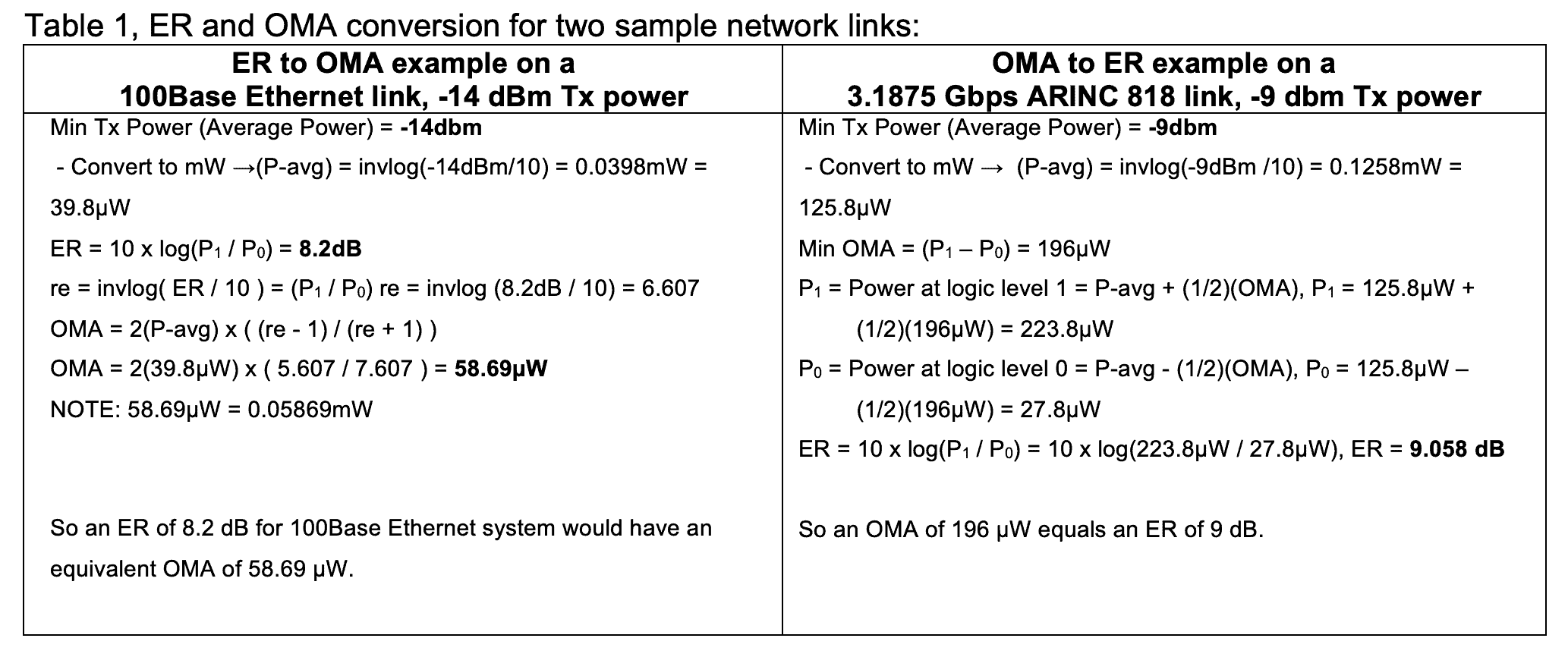
Why use both? There are several different answers to that question. The first answer has to do with protocol. Typically, Ethernet uses ER in its specifications, while Fiber Channel typically uses OMA. The next answer has to do with how the laser is driven. For a high ER, P0 must be low. This is acceptable at slow speeds but requires more power to turn the laser on, and at high speeds can cause issues with the integrity of the signal. It also means that the average power can only be so high, because as average power rises, P0 also rises. OMA can be high at high or low average powers and when ER is high or low. This is more conducive to currently available receivers and transmitters. Receivers now can determine between high and low power levels as long as there is a great enough difference between them as opposed to older generations where they could better determine ‘light on, light off.’ Transmitters can now perform better when modulated between two levels as opposed to ‘light on, light off’. In just several years, the possible output power of all major laser types, VCSEL, FP, and DFB has increased. It is also harder to achieve “light off” as the speed increases because the light is “off” for shorter and shorter periods. OMA and ER are both valid and relevant ways to determine whether an optical data link will work or not, but the application determines which will be used to test a link in a given system. It is also possible to convert between the two and use them to determine P1 and P0. Below are sample calculations using real specifications to show the formulas and calculations:

Table 1 shows conversion calculations of two COTSWORKS parts. The column on the left has calculations that convert ER to OMA specifications from a 100BaseX transceiver that communicates using 100 Mbps Ethernet. The column on the right contains calculations that convert OMA to ER specifications for a 3.1875 Gbps transceiver using the ARINC 818 protocol. As stated above, both ER and OMA are current and valid ways to determine the conformance of an optical module. While they both define a relationship between high and low power levels, they are not interchangeable except through mathematical conversion and even then, the results are still just very good approximations due to round off errors and significant figures. Most importantly, however, the output powers of both systems shown are the minimum power, so the calculations change as Tx power goes up. Several years ago this wasn’t as much a factor as it is today with laser manufacturers achieving the highest output powers possible for FDA Class 1 eye-safe devices. OMA is a more effective way to measure signal variations as output power goes up and speed increases since receivers can now determine differences instead of ratios. It is very important to decide which is applicable to a given situation and to stay consistent throughout. This applies not only to design and systems-level integration but becomes even more important in qualification and production testing. It is important to define the correct measurement and the correct way to test a part so that measurement is accurate and truly represents the device under test.